Guide to the world of hydraulic sealing II.
This article will describe the basic influences and parameters to be considered when designing seals for hydraulics. We will get into the physics and theoretical knowledge that is the basis for the design of seals depending on the operating conditions.
Mechanics of seals
The requirement for seals on hydraulic cylinders is to prevent fluid flow over two surfaces in relative motion and to maintain a high level of sealing performance over its lifetime and under the operating conditions for which it was designed.
During the sliding motion, a drift flow develops and due to the hydrodynamic pressure build-up, the seal lifts off the guide surface and a thin liquid film remains between the seal and the guide surface. The thickness of this liquid film is regulated by the following formula:

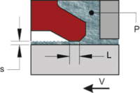
The amount of fluid passing through the seal during movement can be thought of as something like leakage.
Pressure
The pressures acting on the seals are those induced by the hydraulic pump (Pp) and those caused by the cylinder movement called “drift pressure” (Pt):

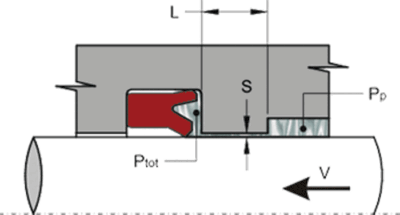
The drift pressure, especially in tight fitting cases, can sometimes be higher than the pressure generated by the pump itself, causing rapid seal damage. During operation, the sealing element can be subjected to various constant pressures which can reach very high intensities even over a short period of time. These additional loads, expose the seal to high operating stresses. When selecting the right sealing system, these must be taken into account.
PRESSURE LOAD – LESS THAN 50 Bar
Low pressure is the most critical situation for good sealing system performance and is a situation where major leakage problems can occur. In these cases, the seal blades are not sufficiently expanded by the fluid and the oil film between the edge and the dynamic surface reaches an excessive thickness. Choosing the right seal profile and material can greatly reduce the risk of leakage in such a situation.
MEDIUM PRESSURE – 50 to 150 Bar
The pressure range between 50 and 150 bar is one of the most favourable and under such conditions almost all seal types guarantee good performance, even with different lifetimes depending on the seal material.
HIGH PRESSURE – OVER 150 Bar
At high pressure or high pressure surges (shock loads), the seal normally gives good results.
The pressure of the fluid itself activates the seal blades and thus ensures very good sealing performance. High pressure, on the other hand.
reduces the service life of the entire sealing system. Under these working conditions, many cases of wear and extrusion occur, causing premature seal failure. The choice of material is very important because it must be resistant to extrusion and wear.
Speed
The velocity between the seal and the moving surface is a critical factor that must be considered when selecting a seal and has an important effect on the performance of the sealing system. The seepage can be considered proportional to the square root of the velocity although this cannot be accurately predicted as it depends on many other factors ranging from the appropriate choice of seal, type of fluid, temperature and surface quality.

Vertical axis: seepage
Horizontal axis: speed
LOW SPEED – LESS THAN 0.05 M/S
At low speeds there are no leakage problems, but there are likely to be problems with rapid wear and irregular stick-slip movements. In the low speed range, the hydraulic pressure generated by the movement is not sufficient to form a permanent film of fluid and the seal lip comes into direct contact with the sliding surface, increasing the risk of rapid wear and irregular movement. “Stick-slip”, is a noisy vibratory motion caused by repeated sticking and squeezing between the seal and the sliding surface. Proper selection of seal profile and material (e.g. PTFE, low coefficient of friction) can reduce the problem and also improve fluid and speed control.
MEAN SPEED – 0,05 ÷ 0,3 M/S
This is an ideal situation where there are neither irregular movements nor excessive losses typical of high speed. Under these conditions, the hydraulic pressure generated by the movement is able to ensure a continuous film of fluid between the seal lip and the guide surface, thus ensuring precise fluid control and proper seal lubrication. The thickness of the liquid film, proportional to the square root of the velocity, will generally not reach a thickness capable of causing unintentional seepage.
HIGH SPEED – ABOVE 0.3 M/S
As the hydraulic pressure generated by the movement increases, the seal lifts off the guiding surface, allowing excessive fluid to pass through. The situation becomes particularly critical when low pressure phases are associated with high velocity. In this case, the seal is subject to deformation. Under such conditions
it is necessary to choose a seal that ensures sufficient tightness even in the absence of pressure.
Temperature
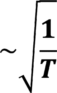
The temperature of the system is a critical factor that must be taken into account when selecting seals and has an important influence on the extent of losses. As a result of friction, the temperature at the edges of the seal is higher than the system temperature, although this cannot be accurately predicted in advance as it depends on many other factors ranging from material, seal profile, fluid type and surface quality. Since the viscosity of the liquid is inversely proportional to temperature, the seepage can be considered proportional to the square root of the inverse of the temperature (see chapter “Mechanics of seals”):
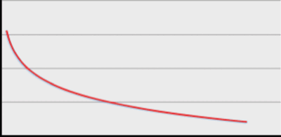
Vertical axis: seepage
Horizontal axis: temperature
LOW TEMPERATURE
At low fluid temperatures, the hardness of the seal material increases and the seal loses its elasticity, allowing an excessive layer of fluid to pass through.
MEDIUM TEMPERATURE
This is an ideal situation where the fluid has the ideal viscosity to prevent losses through sufficient lubrication. Materials at this temperature do not change their mechanical properties enough to affect the performance of the sealing system.
HIGH TEMPERATURE
The sealing material becomes more elastic, the volume of the seal increases and the viscosity of the fluid decreases, thereby reducing losses. At the same time, however, there is insufficient lubrication and increased wear and risk of irregular movement. Careful attention must be paid to the temperature limits of the materials. At limit values, there is a loss of
the flexibility of the seal.
Friction
Friction between the dynamic seal and the sealing surface depends on many factors such as seal design and material, fluid, pressure, temperature, speed and surface finish.
The resulting frictional load may not be important for many applications (except in pneumatic cylinders where minimal friction is required for optimum performance), but friction itself can be dangerous in terms of heat generation which can cause degradation of the seal material and lubricant film or increase leakage by reducing viscosity. In this sense, seal performance is difficult to analyze in general terms because it depends on a larger number of empirical factors that are typical of seal design.
In general, however, friction is proportional to pressure, but the coefficient of friction can vary with speed, temperature, material and surface finish.
K – empirical factor specific for the shape of the installed seal
μ – coefficient of friction
Pe – Equivalent pressure corresponding to the pressures acting in the system
v – speed
A – Seal contact surface (≈ π – Diameter – Radial cross-section)
Specific values of the K factor are difficult to obtain unless they are evaluated on empirical lines or based on comparative data. This formula can only be used directly to determine possible differences in performance and friction on compression seals of the same type and material but different sizes.
The coefficient of dry friction of typical sealing materials that rub against a smooth and dry sealing surface can be from μ=0.4 ÷ 1. For lubricated surfaces the range is much lower, for example μ=0.02 ÷ 0.10. This is especially true for elastomers. Fabric materials and impregnated fabrics show a similar “μ” value, but with minor differences, for example μ=0.04 ÷ 0.08 when lubricated. In general, the harder the material, the higher the friction, and the softer the material, the lower the friction, but this is well sustainable at low pressure. The coefficient of friction “μ” is also affected by pressure, but a direct relationship is not clearly established. In general, friction will be highest at low pressure, with the lowest values being obtained at higher pressures.
The change in friction at different pressures also depends on the surface treatment, especially the manufacturing method in the case of cylinder and piston seals. The most pronounced increase in friction with increasing working pressure occurs withrougher surfaces and cold-forged structures, compared to ground and polished surfaces.
The conventional design of the rollers is ground, resulting in a precision surface with an average roughness between 0.25 μm and 0.625 μm. The biggest problem for the seal designer is thecurrent tendency to use hydraulic cylinders made directly from drawn pipe without any subsequent modification.
FRICTION AND SPEED
The changes in friction with friction velocity are clearly defined and take place in three phases (see figure below):
– Static friction (direct contact between seal and sealing surface)
– Mixed friction
(mixed dry and liquid friction)
– Liquid friction
(liquid lubricating film between the seal and the sealing surface)

Vertical axis: friction
Horizontal axis: speed
The friction is higher at start-up because it has to overcome the static friction coefficient (area 1). When the speed is increased, a liquid film is inserted between the seal and the dynamic surface to reduce the contact surface and thus friction (area 2). With further increase in speed, the contact surface disappears and friction increases (area 3) due to shear stress.
SEAL WEAR AND LIFE
Due to the different designs and manufacturing of different materials, sealing systems have different behavioural patterns under increasing pressure.
The use of hard material reduces the risk of compression damage. On the other hand, hard material does not have as good sealing properties as soft material, especially at low operating pressures.
For the best sealing system to be effective at high and low operating pressures, seals made from several types of materials with different properties should be used. Ideally, a solid gasket made of several materials that have increasing hardness and can reach maximum hardness at the rear of the gasket where the joint is. However, this is not entirely achievable, even though our seal designs are constructed on the principle of multi-stage with the aim of achieving the ideal.

Vertical axis: seal wear
Horizontal axis: surface roughness
Seals lose their ability to operate due to normal wear of the sealing material. This is greatest at low speeds during start-up and at low speeds, as well as erosion of the seal material caused by fluid flow over the seal surface and impacts at the point of degradation.
The first symptoms can be observed at low pressure, when the seal is unable to maintain the required contact with the sealing surface due to wear. At high pressure, the deformation is more noticeable and the seal meets the requirements as long as the pressure is kept at the same level. Seal life cannot be accurately determined because it depends on many other factors, starting with the appropriate choice of seal for the job and proper installation.
Wear can increase with lack of lubrication, poor quality build-up, excessive friction temperature, too soft seal parts, etc. Normal seal life will vary quite a bit depending on the application, as the recommended acceptable conditions and seal type also vary.
If the seal life is significantly lower than the average for a particular device, the wrong seal has probably been selected and the operating conditions have proven to be significantly more demanding than expected when the seal was selected.
The wear of the seal depends on the surface against which the seal is rubbed; it is therefore greatly influenced by the way the assembly is manufactured. The table shows the seal wear on the cylinder surfaces achieved by the three machining methods.
Seal wear is graded from 0 for no visible wear to 10 for a worn seal. These individual data were obtained after 100,000 cycles of cylinder operation at a working pressure of 250 bar.
It is clear from the table that with a polished cylinder surface in the Ra range of 0.08 μm to 0.7 μm, wear is almost zero. In contrast, cold-forged cylinders with a surface Ra from 0.4 μm to 1.25 μm have maximum wear.
The theoretical introduction of the seal design is over. In the next article we will open the topic of materials, their choice is another essential parameter that determines the functionality of the sealing element.